Raspberry Pi based Extreme Feedback Device
I always wanted one. Wouldn’t that be cool if there was something to scream who’s the next to wear the Bad Code Cowboy Hat, I thought. I had numerous attempts to try and find some gizmos that can be connected via USB and easily controlled with simple programming, but couldn’t quite find anything that would be visible enough or controllable enough to make it all happen.
That changed when a guy I worked with took me through his RaspberryPi controlled heating system. This is when I realised that RPi is exactly what I needed to make it happen.
My first attempt still revolved around USB controllers. Reading many, many articles on the net I thought a HID USB relay would be the perfect answer to my question - all I needed was to simply connect it to Pi, write a little software to read my CI feed and switch between two bulbs to indicate status.
I got one HID relay from evilbay, but I think it was properly chinese, no instructions, no luck in getting the USB driver to do what I wanted.
Through research for new USB relay I found a website of a company called sainsmart.com. These guys are selling plenty of Arduino components for home-automation and stuff. When reading some of their product description I realised that I can possibly use RPIs GPIO and a normal electronically controlled relay to make it happen, and so I did.
The idea for how the system works is illustrated in the chart below.
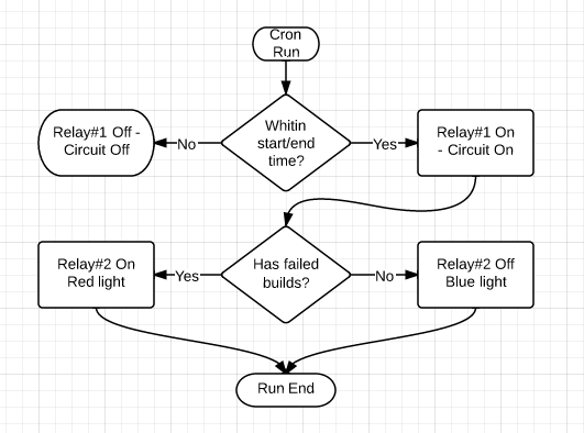
I opted for enabling it only within given times as there was no reason for the unit to glow while nobody is in the office.
Let’s start with the hardware.
You obviously need a Raspberry Pi. I bought mine from Amazon as a starter kit with case, power supply and SD card for about £35. Next, the Sainsmart relay I mentioned, I used one of these (also from Amazon).

Some spare bits like extension lead, jump leads, connector stripes, bulbs etc I will leave to your own creativity.
REMEMBER, THIS PROJECT IS RUNNING ON HIGH VOLTAGE, THIS CAN KILL YOU IF YOU DO A COWBOY JOB OUT OF IT (NO JOKES)!!!
Whatever you do with my instructions, you do at your own risk.
Now that we’ve put it out of the way…
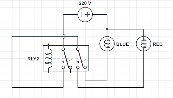
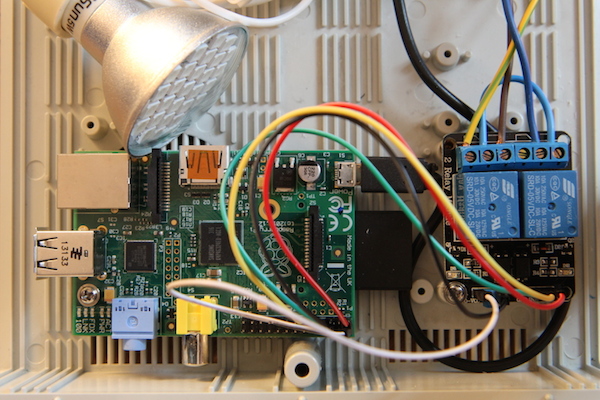
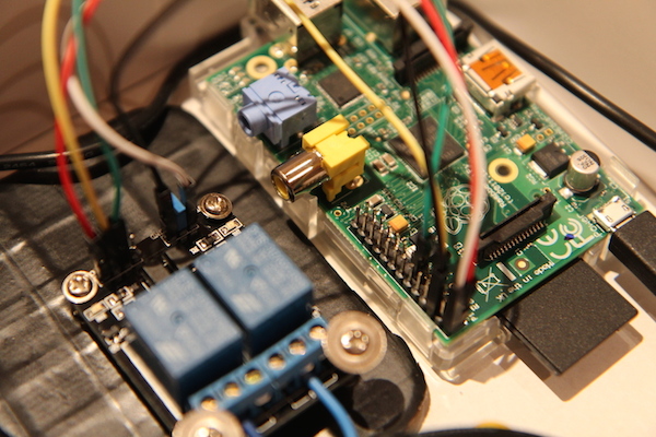
The electric wiring is rather simple, to achieve the on/off functionality you will need to wire one relay out to in of another. The other relay controls the colors.
You will need 5 pins out of RPi GPIO to control the relay. Two will provide 5v current on the circuit that powers relay switches, further three to control switches on/off - two signal and one ground.
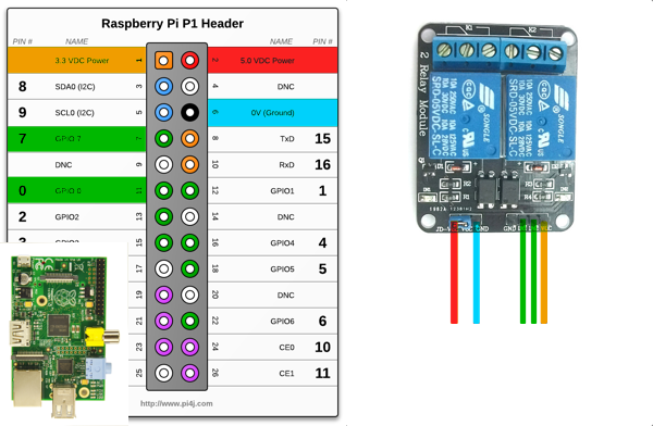
This is how RPi will make the relay do what we want, if you don’t quite understand, don’t worry - trust the force.
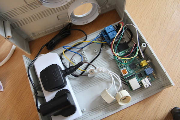
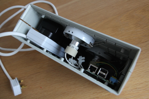
I’ve chosen to house mine in a so called electronic project enclosure. These guys are usually sturdy, with lids, and most importantly fire retardant! I also have some added extras like the LED bulb housing rings to make the whole thing look prettier and easier to assemble.
You should get the idea form below pictures.

Software
To make out RPi life crashless we need to use a R/O filesystem to protect the SD storage. There is one brilliant solution out there called IPE developed by the good folk at NutCom. I strongly recommend you flash your RPi with it, it will save you hassles later and it’s really easy to use (switch from r/o to r/w).
Next, connect the Pi and run all the usual setups, get network running, update apt-get and install RPi python module https://pypi.python.org/pypi/RPi.GPIO. You should be able to either manually do this, use pip/easy_install or even apt-get on that version of IPE. You will need that module to make the RPi chip programming a blast. It will save you time and quite potentially the unit from frying too.
I’m using Atlassian Bamboo (as well as Jenkins) as my CI so the feed reading in my code is specific to it. The idea is simple though, read the feed, if anything failed light the SAD light, otherwise light the HAPPY light.
Have a look here to see what I mean, code is very simple and configuration is explained in the README.md
http://github.com/michael-donat/extreme-feedback-device
Happy hacking!
Edit:
Small watch-it-in-action